Rix SA-6 Rebuild - winter project

Please register or login

Welcome to ScubaBoard, the world's largest scuba diving community. Registration is not required to read the forums, but we encourage you to join. Joining has its benefits and enables you to participate in the discussions.

Benefits of registering include

  • Ability to post and comment on topics and discussions.
  • A Free photo gallery to share your dive photos with the world.
  • You can make this box go away

Joining is quick and easy. Log in or Register now!

maniago

Contributor
Scuba Instructor
Divemaster
Messages
899
Reaction score
288
Location
Mid-Atlantic (MD)
# of dives
I just don't log dives
I've spent some good hours on the lathe cutting out a new crank for my Rix, so I thought I would post a few pics of where I'm headed. Setting up to do the final holes for the balance weights. The second stage AL head I finally got apart today. Needed the shop press to persuade it apart....the head is probably salvageable, but the rusted guts not so much...

Not sure if anyone is interested in any of this, 'cause its a bit outside the norm for this forum. Probably better suited to the HomeMachinist...but those guys don't care about diving! haha :)
 

Attachments

  • IMG_6073.jpg
    IMG_6073.jpg
    45.9 KB · Views: 328
  • IMG_6072.jpg
    IMG_6072.jpg
    48.5 KB · Views: 294
  • IMG_6069.jpg
    IMG_6069.jpg
    50.5 KB · Views: 272
  • IMG_6062.jpg
    IMG_6062.jpg
    36.5 KB · Views: 297
Looks like beautiful work. Will you need to harden the crank where it wears?
 
Thanks. No hardening required. All the surfaces are either bearing pads or pulley pads. That said, the drive pulley keyway on my original was cut off center and the pulley eventually oblonged its pad and walked into the heads and the intercooler tubes. Its had a hard life....
 
Ok, just as a shout out to good folks, I've had lots of help from Eric Zensius and Iain Middlebrook of Rix. Thanks for your patience guys.

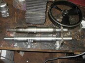
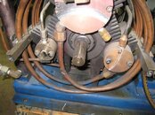
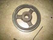
Here's a shot of the heads and drive pulley that started my road less traveled. For those not familiar with a Rix, this is what's behind the drive pulley when you pull it off the crank and thus going clockwise: 3rd, 1st, and 2nd stage heads, crankshaft in the middle. The big frowny face on the 1st stage, vertical line on the 2nd, and the bit-off center plug and allen bolts on the 3rd is not what you want to great you. You can also see a discoloration on the crank if you look close - that's a mix of whats left of the chrome plating and worn base metal. After a lot of thought and some discussion, I decided to TIG weld up the crank journal and recut it. The welding went fine, but it proved to be a mistake. Despite pre- and post heat to 500F, it warped the crank about .010" end to end. Max run out is +/-.0025". I suspect that that's measured with the bearing pads chucked and not and end because that would make sense, but either way, I was out. The crank might have been out before I worked it (not sure) because I didn't natsass mic it properly prior to lighting up. My subsequent rebending efforts proved futile despite some serious hydraulic persuasion, thus I resigned myself to the lathe (a new crank though available, is prohibitive). What I should have done was JB weld the pulley pad and recut that since the stuff is hard as rock, but I realized that about 30mins too late. Curse words and head-slapping followed.....
 

Attachments

  • IMG_1609.jpg
    IMG_1609.jpg
    48.7 KB · Views: 254
  • IMG_1610.jpg
    IMG_1610.jpg
    43.7 KB · Views: 225
Looks like some good work there. Nice to have the machine tools when you need them! So did Rix give you a drawing and material specs for the crank or did you have to measure, copy and correct the original? What kind of steel did you use?
 
Looks like some good work there. Nice to have the machine tools when you need them! So did Rix give you a drawing and material specs for the crank or did you have to measure, copy and correct the original? What kind of steel did you use?

Nah, I was going to ask Eric for that, but he anticipated my question and told me he couldn't. He was able tell me that it was not heat treated and that 1045 mild steel was used, a logical choice for this application IMHO. So plenty of reverse engineering, and common sense choices when things don't seem to measure up right....
 
Sounds like you put some serious hours into it. I'm not a Rix owner, but if you made some drawings, you should post them up. They may come in handy for someone in the future.
 
Well, I guess you could say I made a drawing. Autocad its not, but if it helps someone I suppose have at it. In reality if you have to do this, I'd expect you have your old one anyway to measure from anyway...

Of note, I used 1.75"dia 1045 stock, not 2" as the factory did. It doesn't really matter as the center section only has stops that the bearing centers ride against, and a flat to put a wrench on to hold the crank when torquing the end N-08 nuts. Not having to hog an extra 1/4" on everything is a big deal for my small machine. Perhaps not so if you have a big Southbend....
 

Attachments

  • IMG_6114.jpg
    IMG_6114.jpg
    30 KB · Views: 462
Here's the next few things ready for assembly.

The first pic is the first and second stage cylinder liners. The shiny ones are the new ones I cut down in the lathe. They are just basic sintered bronze from American Sleeve Bearing. A little scotch-bright to get a crosshatch is all that's needed. I went for a ~30deg hatch, since it appeared that was what was on the old ones, and its what you shoot for in hand honing a combustion engine as I remember. Eric told me that there was no telfon coating on the inside of the cylinders as is sometimes done with oil-less compressors, to help seal the rings. In this case, the rings wipe teflon into the bronze until a layer is there, and then should stop. If not, another set of rings and you're GTG. I did the hatch in the lathe with my hand stuck in the barrel as it was turning. Good way to break your arm off, so I'm typing this with my toes (just kidding) :)

Last two pics are of the third stage connecting rod and the replacement of the Heim joint. Required a bit of cutting down and a center lube hole drilled in the joint to match the old one in the upper right of the pic. Straight forward. First and second stage rods got new Heim joints also.

The last two pics are a mocked up compressor head, and how this thing is supposed to start to come together on its base plate - one day soon I hope!
IMG_6129.jpgIMG_6131.jpgIMG_6132.jpgIMG_6107.jpgIMG_6139.jpg
 
https://www.shearwater.com/products/swift/

Back
Top Bottom