You are using an out of date browser. It may not display this or other websites correctly.
You should upgrade or use an alternative browser.
You should upgrade or use an alternative browser.
Need advice on building a cascade fill panel
- Thread starter Topbodz
- Start date
Please register or login
Welcome to ScubaBoard, the world's largest scuba diving community. Registration is not required to read the forums, but we encourage you to join. Joining has its benefits and enables you to participate in the discussions.
Benefits of registering include
- Ability to post and comment on topics and discussions.
- A Free photo gallery to share your dive photos with the world.
- You can make this box go away
Wookie
Proud to be a Chaos Muppet
Staff member
ScubaBoard Business Sponsor
ScubaBoard Supporter
Scuba Instructor
I have built many of them. Inside or outside, exposed to sun and weather or not, how good are you with a tube bender? The smaller the size, the more precise your bending has to be. As far as fittings go, try here for stainless or here for plated. My regulators, reliefs, etc. come from Aqua Environment, and my panel mount valves are Sherwoods so that I use the same rebuild kits for cylinder valves as I do for panel valves. I will happily send you pictures front and back if you are interested. I use Class 1 gauges because I have more money than sense, there is no reason not to use Wika, except my panels were cut for Class 1.
Here are a few thoughts if you are new to this. The first instinct is to panel mount everything to hide and protect the tubing. The problem is it can make leak checking and repairs very difficult if you don't have access to the back. It can also make figuring out tube routing difficult if you don’t provide flow lines and labels on the front of the panel.
Mounting all the components can be a bit expensive in brackets, panels, and tube fittings. Sometimes it is better to surface mount everything on a brass manifold that all the valves and gauges screw into. That solves the mounting problem, can be very compact, and can look better than a gaggle of ¼ tube fittings. There are a few manifolds on the market or you can have a local machine shop bore and tap holes in a block of brass. Just make sure there is enough room between ports to screw the components into and the centers fit your hands to operate valves.
Stainless steel pipe fittings are notorious for Galling. Even if you avoid galling, stainless to stainless tapered pipe threads are harder to seal. Whenever possible I prefer to design so that stainless pipe threads screw into brass.
Compression tube fittings are the easiest to use since they don't require much tube prep, skill, or special tools. The disadvantages over 37° flared or flat-faced O-ring sealed fittings are they don’t take well to multiple reconnect cycles and require a lot of insertion distance. The insertion distance can make it much more difficult to remove a section of tubing from an assembly for repairs.
It is never a good idea to hang a component supported only by tubing. It is also considered a poor practice to interconnect mechanically mounted components like valves with a straight piece of tubing. The reason is it puts strain on the components as they expand and contract with pressure and temperature. That strain causes leaks and tube failures.
Carefully check the operating pressure on every component because not all stainless handles 6000 PSI. You can use lower pressure components on the outlet side of a regulator, but you require a pressure relieve valve for when the regulator fails.
In this application, a self-venting regulator is more convenient than a non-venting. Basically a self-venting regulator bleeds the pressure off on the reduced pressure side when you lower the setting. Otherwise you have to manually bleed off the pressure as the regulator pressure is reduced.
Don’t assume that a ¼ compression fitting from one manufacturer has the same working pressure as another. Also, not all compression fittings are interchangeable. It can be a real PITA to have a Swagelok compression fitting on one end of a tube and a CPI on the other. I believe that Hoke/Gyrolok and Swagelok are the only ones that are.
Wookie
Proud to be a Chaos Muppet
Staff member
ScubaBoard Business Sponsor
ScubaBoard Supporter
Scuba Instructor
To expand on what Akimbo said, I don't have a machine shop build my panels, I do it myself out if 1/4" Starboard. UV resistant (but not -proof, I replace the starboard every 10 years or so, but they are out on the deck of a dive boat), easy to work yourself with a good set of hole-saws, and if you screw up a cut, cheap enough to throw the whole thing out and start again. I have a frame welded to the overhead of the sundeck that the Starboard mounts to with 1/4" oval head machine screws and cup washers with nylock nuts.
If you choose Swagelok or Hoke fittings, the nuts and ferrules are indeed interchangeable (Hoke will say this, Swagelok will not, but they are) and they are the Cadillac of fittings, and are all I use on my panels. Get the silver plated ones (what's an extra 2 bucks when you're buying $12 fittings) that don't gall.
If you choose Swagelok or Hoke fittings, the nuts and ferrules are indeed interchangeable (Hoke will say this, Swagelok will not, but they are) and they are the Cadillac of fittings, and are all I use on my panels. Get the silver plated ones (what's an extra 2 bucks when you're buying $12 fittings) that don't gall.
I am new, and only have limited experience in this and there is not much info in your post so maybe I am just rambling on.
I guess the main question is are you building a bank system or a cascade system? From my understanding bank systems are used when there is a compressor directly connected to the system (like at our dive locker) and cascade systems when the bottles are stand alone (like our O2 cascade at work, or at some of our remote fire stations).
If you are trying to build a multi bank system with a compressor then I have nothing to add.
If you are building a cascade system I am not sure I understand the point of doing it in "banks". With cascade generally you need a minimum of 3 "tanks" but the more you add the more efficient the system will be. For example at work we have a 7 tank system and it is no problem to get our cascade tanks to under 500psi and still have good fills by the time you get to the 7th tank. If you build a cascade in banks that is going to leave you with lots of volume of gas that is basically unable to be used. If you do 4 "banks" in a cascade system you basically are limiting you system to 4 "tanks" which is less efficient then 5, or 6 , or 12.
At work our 7 tank system has 1 psi gauge and one main shut off. There is a single pipe running along the wall with 7 "T" and 1 elbow, each one with a flexible whip going to a tank. Off the end of the last "T" is the main shut off, then the psi gauge, then the fill whip. With our system you hook up the the tank to be filled and turn it on. The PSI gauge will show the pressure so you know what cascade tank to start with. Each cascade tank is labeled with the final pressure after the last use. You could go either way, but our lowest tank is on the right and highest on the left. So you open the valve on the right tank until the psi equalizes and that number is recorded on the tank (masking tape label). Then you move left one tank and repeat the process until the tank is full. When the psi in the the far right tank is to low to be useful, in our case generally under 500 psi, it is taken out and all tanks shift right one place and a full one is added at the far left.
Just some thoughts.
Id love some pictures. you can either post them here or email to scubatankservices@gmail.com
thanks for your input.
---------- Post added November 23rd, 2013 at 02:50 PM ----------
Want to thank everyone for their input. and im still looking for more advice...
particularly on the fittings to use brass or ss., and pictures or drawinauge. gs of the piping system...
I guess the standard is 4 pressure gauges for the banks, a regulator and one Fill pressure gauge.
I have 12 cylinders, for 4 bank of 3. may get 4 more cylinders for 4 bank of 4...
how would I split up the fill pressure from each banks?
thanks again
thanks for your input.
I have built many of them. Inside or outside, exposed to sun and weather or not, how good are you with a tube bender? The smaller the size, the more precise your bending has to be. As far as fittings go, try here for stainless or here for plated. My regulators, reliefs, etc. come from Aqua Environment, and my panel mount valves are Sherwoods so that I use the same rebuild kits for cylinder valves as I do for panel valves. I will happily send you pictures front and back if you are interested. I use Class 1 gauges because I have more money than sense, there is no reason not to use Wika, except my panels were cut for Class 1.
---------- Post added November 23rd, 2013 at 02:50 PM ----------
Want to thank everyone for their input. and im still looking for more advice...
particularly on the fittings to use brass or ss., and pictures or drawinauge. gs of the piping system...
I guess the standard is 4 pressure gauges for the banks, a regulator and one Fill pressure gauge.
I have 12 cylinders, for 4 bank of 3. may get 4 more cylinders for 4 bank of 4...
how would I split up the fill pressure from each banks?
thanks again
Wookie
Proud to be a Chaos Muppet
Staff member
ScubaBoard Business Sponsor
ScubaBoard Supporter
Scuba Instructor
So, a little explanation is needed. Gas comes in from one of 2 compressors. That decision is made in the compressor room, where either identical compressor can make air or nitrox. I have taken pictures of the nitrox panel, the air panel is identical. The gas comes up into the 3 way valve (to Banks/Direct Fill) and goes either back to the banks (8 total 4500 PSI cylinders, 4 banks of 2 cylinders each) or directly to the regulator. The inlet of the regulator has a inlet pressure gauge, which will be the same as whatever bank you are filling from, or the same as the discharge of the air compressor, the outlet of the regulator (the 4" gauge) measures fill pressure in the whips. If the 3 way valve is directed To Banks, the gas goes back down to the compressor room through a series of check valves and automatically fills the lowest bank first. Each bank has a line up to the fill panel so that each bank may individually fill a cylinder, starting with Bank 1. When the first bank is exhausted, the compressor automatically fills the low bank (1) while the operator is filling from bank 2 etc. I will try to find a flow diagram if this confuses you (it confused me for the first 3 years I used it, and I built it. I did not design it, however). This has been in place on this boat since 1998.
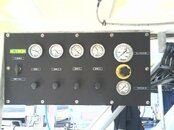
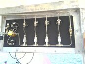
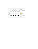


…
particularly on the fittings to use brass or ss., and pictures or drawinauge. gs of the piping system...
Compression fittings (Swagelok style) requires that you use the same material for the tubing and fitting. That often makes the choice for you. You can mix stainless tubing and brass with 37° flared fittings. You need to look a pressure ratings for both.
Here is a guide for tubing:
http://www.swagelok.com/downloads/WebCatalogs/EN/MS-01-107.pdf
Here is a tube fitting catalog:
http://www.swagelok.com/downloads/WebCatalogs/EN/MS-01-140.pdf
… I guess the standard is 4 pressure gauges for the banks, a regulator and one Fill pressure gauge.
I have 12 cylinders, for 4 bank of 3. may get 4 more cylinders for 4 bank of 4...
how would I split up the fill pressure from each banks?...
You need to do the math. I am guessing that your objective for using a cascade system is to minimize how much you have to run (start and stop really) your compressor and speed filling operations.
Make a spreadsheet that calculates the pressure drop in each bank, the number of Scuba cylinders you want to charge at once, and your compressor capacity. You also have to decide if you want to be able to charge cascade cylinders off the compressor at the same time. If yes, do you want to fill from high-low or low to high banks. Low-high is easy with check valves and simple for operators, but less efficient since keeping the highest bank above the Scuba cylinder pressure dictates when you have to start filling directly off the compressor.
Why don’t you post a schematic of what you want to do and let us make suggestions from there.
Nice panel that would work I suppose. I wonder about the check valve set up for filling the banks.
and since it fills the lowest bank first (most likely bank 1) what happens when bank 1 reaches the same pressure as bank 2, does it then fill bank 1 and bank 2 until they reach max pressure?
do you have a schematic of the banks piping?
what size tubing did you use? and which compression fittings? i'm assuming that those are check valves on top of the bottom tees?
what would be a good pipe bender to use for this application?
thanks
---------- Post added November 24th, 2013 at 08:19 AM ----------
Thanks for those links.
Im not 100% sure how I want to do it yet. But I do like Wookie's panel & the 3 way valve so I can fill for the banks or the compressor....
typically I would fill 2 to 4 scuba cyl at a time from the banks and just let the compressor refill the banks (at night ) when they get low...
I do have 8 whips, so once in a while I do fill 8 thanks at a time from the compressor, but it takes a while. On the flip side they are just lukewarm when filled...
the compressor is a Mako 20.8 cfm, 6000 PSI unit.
Compression fittings (Swagelok style) requires that you use the same material for the tubing and fitting. That often makes the choice for you. You can mix stainless tubing and brass with 37° flared fittings. You need to look a pressure ratings for both.
Here is a guide for tubing:
http://www.swagelok.com/downloads/WebCatalogs/EN/MS-01-107.pdf
Here is a tube fitting catalog:
http://www.swagelok.com/downloads/WebCatalogs/EN/MS-01-140.pdf
You need to do the math. I am guessing that your objective for using a cascade system is to minimize how much you have to run (start and stop really) your compressor and speed filling operations.
Make a spreadsheet that calculates the pressure drop in each bank, the number of Scuba cylinders you want to charge at once, and your compressor capacity. You also have to decide if you want to be able to charge cascade cylinders off the compressor at the same time. If yes, do you want to fill from high-low or low to high banks. Low-high is easy with check valves and simple for operators, but less efficient since keeping the highest bank above the Scuba cylinder pressure dictates when you have to start filling directly off the compressor.
Why don’t you post a schematic of what you want to do and let us make suggestions from there.
Wookie
Proud to be a Chaos Muppet
Staff member
ScubaBoard Business Sponsor
ScubaBoard Supporter
Scuba Instructor
See if this explains anything. If worse comes to worse, I'm in Key West, not that far from Hollywood.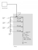 All tubing is 1/4" 316L .049 wall made up with Swagelok compression fittings. Swagelok makes the best tubing bender. Get the 1/4" tube bender with the blue handles and the rollers on the bender dies. They will prevent crimping. It's about 3 times as expensive as the cheapie from Grainger, but it's awesome.
Those are not check valves above the bottom tees, but the back side of the sherwood panel mount line valves.
 All tubing is 1/4" 316L .049 wall made up with Swagelok compression fittings. Swagelok makes the best tubing bender. Get the 1/4" tube bender with the blue handles and the rollers on the bender dies. They will prevent crimping. It's about 3 times as expensive as the cheapie from Grainger, but it's awesome.
Those are not check valves above the bottom tees, but the back side of the sherwood panel mount line valves.
Similar threads
- Replies
- 8
- Views
- 799
- Replies
- 126
- Views
- 11,104
- Replies
- 24
- Views
- 2,088
- Replies
- 10
- Views
- 1,663
- Replies
- 10
- Views
- 801


