Rix SA-6 Rebuild - winter project

Please register or login

Welcome to ScubaBoard, the world's largest scuba diving community. Registration is not required to read the forums, but we encourage you to join. Joining has its benefits and enables you to participate in the discussions.

Benefits of registering include

  • Ability to post and comment on topics and discussions.
  • A Free photo gallery to share your dive photos with the world.
  • You can make this box go away

Joining is quick and easy. Log in or Register now!

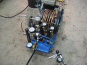
Finally got into the plumbing work. I decided to go back to copper. Working pressures for ACR copper are basically about 1000psi, but its way way conservative - burst pressures even at 350degs are ~8000psi. They spec low because the piping on ACR systems just don't get servicing during their some 20 yrs of bobbing about on a roof somewhere. Given that its pretty cheap to get vs stainless ie as easy as walking into Home Depot, I can afford to replace it if I have to. Same goes with brass fittings, though you have to pay attention to anything that's cast, like T's and X's. Still they are overly conservative too, being cut from solid bar stock. 314SS stuff, especially Swage-lok, is super nice, but expensive and a PITA to get. I'll keep a stink-eye on this area just incase.

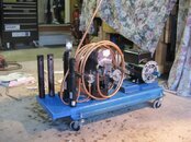
I was toying with building a wild-leg transformer for the 3phase motor I have, but the cost of doing that vs buying a new single phase 5hp was a wash. So I went single phase. I also picked up a magnetic starter that will accept a high pressure switch. I'll probably still make the transformer, but that'll be a later project.

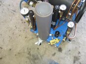
My second stage head has some good rust in it, so in this compressors former life it was making first stage water. Its not supposed to do that if pressures and temp are in spec, but I lucked into got two more used Rix coalescers, so plumbing is now one for each stage, with two for the third stage. Had to weld up an extension for the extra coalescers...
 

Attachments

  • IMG_6165.jpg
    IMG_6165.jpg
    52.8 KB · Views: 277
I think that copper is going to swell on you
 
I think that copper is going to swell on you

Yeah I doubt it. 1st stage pressure is ~150 psi, 2nd is ~650. Well with in working pressure for the sized ACR tube required. 3rd is where I might be pushing it, but Rix originally used ACR copper on all stages on their first 6000 units, then transitioned to SS due to fretting issues...
 
The use of copper tube was for the A build units, but in addition be aware that copper tube will also "work harden" over time and crack or shear either just below the ferrule nut. It can also can wear thin very quickly where it meets the coil clamps each side of the block and also any point that is touching. Wrap the inside edges of the tube clamps with fibreglass heat insulation tape or they will "rattle" and fail early

Both soft tube coils and "half hard" copper straight tube lengths have been used in the past, cant say I like either but its easy to bend and a very cheap compared to the stainless steel Mil spec SAE fittings and tube, a factor of a tenth the price.

Note stainless SAE type nuts are used (not ordinary twin ferrule Swagelok type) as the nut is longer and supports the tube over a longer length reducing the shear point. A minor point but a valid consideration when vibration is a factor.

IMHO the 1st stage coaleser is of limited value but for one advantage in that if you now have a spare port to fit a pressure gauge.

1st stage pressure is around 100 psi so a 200 pig gauge would be ideal
In the event of a loss of pressure in the 1st stage, by 0-ring, head gasket, cooling coil you can easily and quickly resolve the problem without running the pump on low 1st stage pressure and increasing temperatures on stages 2 and 3 causing overheat and subsequent premature ring life failure.

IMHO a full range of displayed interstage pressures is high on my list of essential items for a useful pump.

Also that balance weight on the flywheel end (when facing up) needs to be handed opposite to the one on the fan end (facing down) as well as the swash plate housing in the correct orientation

As your using a non standard driven pulley I guess its balanced therefore the balancing weights need to be opposite each other. From your photo with that drive end weight facing up, then the fan end weight need to be facing down NB when the 1st stage piston is at maximum stroke.

Be careful also not to assemble the wobble bearing housing upside down or it will shake itself apart

I guess its a bit late to check the crankshaft groove positions, you can see from your photos that flywheel has drifted into the heads in the past and they have put the balance inboard I guess to avoid it happening again. Iain
 
Thanks Iain - I was hoping you'd catch this thread at some time. A few clarifications on what you wrote please?

From your photo with that drive end weight facing up, then the fan end weight need to be facing down NB when the 1st stage piston is at maximum stroke.

Ok, I need some help with your definition of "maximum stroke" - ie when the 1st stage is at the bottom of its stroke, which weight is up and which down? Is the head side weight down and the wobble side up? That's how it was when I got it, but I'd like to verify that's correct.

As your using a non standard driven pulley I guess its balanced therefore the balancing weights need to be opposite each other.

Yes I balanced it neutral.

Be careful also not to assemble the wobble bearing housing upside down or it will shake itself apart

I'm not sure how it could ever be assembled upside down - the 2nd and 3rd stage Heim joint bolt holes are about 110 degs from the 1st stage. And the thrust bearing bolt hole has no guide pin holes on either side of it. Can you explain further what you mean "upside down"?

I guess its a bit late to check the crankshaft groove positions, you can see from your photos that flywheel has drifted into the heads in the past and they have put the balance inboard I guess to avoid it happening again. Iain

Yes, I did this on the crank that I mfg'ed from stock, as well as lengthened the shaft. That allows the 10" flywheel to clear the heads.

Thanks for your help! Mani
 
1. Max stroke is the piston fully inside the liner.
TDC Top dead centre, the term used if with a conventional compressor design

2. Back to front, would be better to say than upside down, you will notice the main bearing fits inside the two halves
of the ring inner bearing part 64-B2112 you can't strictly speaking fit it upside down as the 1/4 keyway prevents you.
But you can in error fit it back to front, ie the 1st stage piston is out when it should be in LOL

3. if you have a manual look at drawing B2969-1D its also described as figure 7-1a compressor cross section
You will see there the 1st stage position and the weights positioned all in relation

If you need a drawing I can post.

Also with fitting the main bearings again IMHO use the SKF Explorer range type 6313-2RS1 also get it with a C3 clearance
it will fit like a glove and save a lot of heating. Don't use anything cheap, or Italian or Chinese or Korean
Also be aware a lot of counterfeit SKF is available so use a reputable SKF distributor supplier and not the Ebay rubbish

Another point is you are aware that the two main shaft bearings are not standard and you will need to grind a small
ground "landing: on the outer race, this allows the two Half dog set screws 1/4-20 UNF x 3/4" long to locate the outer race
and prevent it from rotating inside the block. Part 106-16 item 27 on the drawing. Iain

---------- Post added January 21st, 2014 at 09:05 PM ----------

HSM-309008_zpsbb39bba9.jpg


Photo showing swash plate position and 1st stage piston in relation to thrust rider and counter weight
Also you can see the fibreglass tape on the tube clamps tubing blocks.

The timer is vintage Heuer Monti Carlo stop watch ripped off an old saturation dive control van
and used to live jumbled inside my tool box until I found out its worth more than the tools

Photo taken in the days of "time management" we had one hour to build up to as you see LOL Iain
 
Yes - the pic is magic, and helps significantly. Thanks. TDC is a good term on both sides of the pond, especially wrt engine building etal.

I verified the wobble bearing halves, and they are correct. I'd marked them inner and outer when I disassembled. That said, I don't trust anything on this unit to be correct since its been rebuilt before by some ham-fisted lunatic with a screwdriver and a sledge hammer.

BUT, I do have my wobble bearing carrier the other way around ie open end & retainer ring are towards the block, not away like in your pic. Again, it came that way. Is that an issue? I've reset the piston deck heights so unless the 2nd and 3rd stage bores are not the same degrees off vertical, this should be ok. I didn't measure an angular difference...

Yes, I caught the indexing grind on the main bearings, and the fretting tape; thanks for making sure. I went with all SKF bearings, and all my fits were smooth finger press fit. Nice!

Despite what mgt says, the Time&Motion Man is never your friend! haha :)

Mani.
 
Here's a few pics of the plumbing assembly before I tore it all apart yesterday and put all the fittings and valves through the ultrasonic for O2 prep. I still need a new 2nd stage head which is on its way. Of interest, I got a new 3rd stage head from Rix and vacillated on putting it in the cleaner or just bolting it on. In the end I took it apart, and it was filthy. Word to the wise. Also of note, all the valve gear from Aqua Environmental is stated as not O2 compatible. Their reasoning is they use AL for all their blocks, and it gets squirrelly in the presence of 100% O2. I failed to ask them what AL they use, though I suspect 6061. I need to ask that. Same goes with Rix's pistons (which I suspect are also a wrought grade AL).

I'm going to change the gauges to back mount - easier to read than these pedestal mount ones. Also going to add a pull fan on the wobble bearing side. That's probably overkill, but cheap to do, and I keyed and threaded that end anyway.


IMG_6167.jpgIMG_6168.jpgIMG_6169.jpg
 
Houston, we have a compressor! Up and pumping with an hour on the Hobbs meter now.

Took a few days to noodle through all the leaks. Lots of connections. But with 3000psi at the 3rd stage, I'm getting 85 on the 1st and 550 on the 2nd stage, which is book according to Rix. I've taken it to about 4000, so I know there's more headroom if needed.

I still to noodle through the 3rd stage relief valve as its got a leak, but the electric pressure cut out is doing its job, and thus double duty right now. I'll run it for about 5 hrs in bleed off at 3500, then hook up a tank and send off a sample. By then the telfon rings should have done a good job transferring to the cylinder walls, I hope. Seems to like having the cover off better than on - runs a bunch cooler - the last coil in the first and second stage is nice and cool; first coil for both is a fire poker; stinky hot with the cover on too, so the ducting effect is not working properly. Not a show stopper though.

Looking back I think I've put maybe 200hrs of work in rebuilding this compressor, counting research/reading (alot), buying and making parts (more than alot), dis-assembly, cleaning, reassembly, troubleshooting etc. I brought it home 2 Oct, and today I could fill tanks if I needed, 4 months later. Not too bad for a winter project! :)
 

Attachments

  • IMG_6191.jpg
    IMG_6191.jpg
    40.7 KB · Views: 226
As is typical with a project like this, two steps forward, one back. Here's the latest look at the filter stack end of business (thanks to all who contributed to that threads questions - http://www.scubaboard.com/forums/co...6410-diy-compressor-filter-dryer-designs.html )

I still have to finish the plumbing work so this is my first take on trying to fit all this on the real-estate extension I built without going off board - I still want to keep this as a self contained unit for those eventual snowbird trips...:D
 

Attachments

  • IMG_6286.jpg
    IMG_6286.jpg
    43.9 KB · Views: 225
https://www.shearwater.com/products/swift/

Back
Top Bottom