Cool pics!
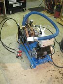
Its actually agonizingly slow watching the filter tower come up to pressure, not the 3rd stage and the coalescers. But the comment on rpm is on point - I have a variable pulley on the motor and I have it set to the lowest point, so the compressor is not running at spec speed yet ~1200 rpm - on purpose testing wise, though I might just leave it there if the fill rate isn't much slower. I'm only filling for myself anyway.
The filter tower was about $600, so not much less than what I might get from a named supplier and Jim has a very good reputation in the compressor rebuild industry, so I would be surprised if anything of his is not top notch. Same if I was in the UK buying from you, eh ol'bean?
")
Thoughts on what BPR pressure points I should set at for the coalescers and 3rd stage piston; and the set on the downstream filter stack?
Agreed if the filter stack is new and from a known source then quite agree its good to go, although with forums you have to points out all the pitfalls just in case.
Although "old' bean" in the UK for $600 (£375 GBP)we would have to have included the BPR with integral check valve and enough 1/4" ports for two charging take offs and a pressure gauge.
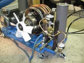
The BPR setting is a bit of a balance, 150 barg 1500 psig is about right balance wise. However if you increase it to say 200 barg 3000 psig then your filter chemical lasts longer as more moisture is "knocked" out at the separator rather than have to carry over to the filter chemical. Great sale pitch for the filter boys, however the pump has to run up to 3000 psig all the time and this has a knock on effect with higher and more frequent service and maintenance costs, Not so great for the pump boys.
Hence the 150/2000 pressure balance, enough back pressure to knock most of the moisture out while the pump runs up around half way on the charging side.
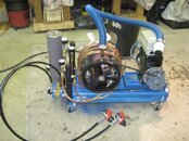
While I'm at this just a comment on your adding that 1st stage discharge separator, and this small condensate your collecting, Now while there is nothing wrong per say with it although you should realise that all that moisture you collected would have dropped out anyway at the 2nd stage separator, for less parts.
Conversely we have built SA pumps for special air applications that we inject distilled water into the 1st stage head to reduce the head discharge gas temperature and
the interstage approach temp this reduces the discharge gas temp by 50%, yet the same moisture is knocked out by the same separators 2nd and 3rd, just auto drained more
frequent using the same dwell just a shorter pulse.
Your 1200 rpm also is fine, reducing RPM reduces flow and cooling fan RPM but again its just about equals out.
Half the speed is half the flow but also half the heat required to dissipate.
Again have done them as low as 300 rpm 1.1 scfm Iain
---------- Post added March 21st, 2014 at 02:45 PM ----------
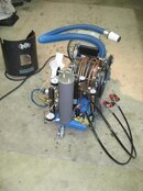
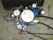
I do like your blue air intake hose, very very nice almost like "Cooper hoses"
Its a bigger bore, therefore less pressure drop and less pulsation, almost temped to try a metre or two LOL
Much better than our stock 1"OD 3/4"ID PVC reinforced tubing, less prone to collapsing and kinking when you have to roll out the 15 foot stock length.
The air intake filter at the end is also very interesting, looks like an automotive part
The Rix stock air filter is custom built ugly can of tin, built special to a mil spec for USN its hugely overpriced and still only a plated tin shell, with a pleated element.
This is an area I think we should explore further. Even with a lower dP the larger bore intake hose compensates acting as a pulsation dampener. It looks good too.
On the performance side the 3/4" bore Rix tube with a one meter 3 foot tube length will give a higher charging rate than either no intake hose air filter direct mounted or any other length up to 15 foot.
There is a good article here if we ever need get sidetracked from compressors LOL
Exhaust System Technology: Science and Implementation of High Performance Exhaust Systems
All the best. Iain