

Jeff_O
Contributor
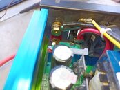
A 600 watt continuous 1200 watt surge current pure sine wave inverter I have I was cleaning dust out and had seen 2 fuse holders in parallel. Inserted into both fuse holders were 30 amp fuses.
I know where separately two fuses are used, for separate fused hot and ground. I accepted that it can better protect the circuit. If one can give more on this great, I would appreciate that.
Is there a reason that can be explained for paralleling fuses?
I do understand that in parallel the current that would split, would be close to equal through the two fuses. If that is correct then would just one fuse be essentially the same by doubling the amps. Don't use two 30 amp fuses in parallel, just use a single 60 amp fuses instead? They are available I would think.
I did search internet and didn't find something that was easily explaining parallel fuses, so thanks if you have answers.