My portables

Please register or login

Welcome to ScubaBoard, the world's largest scuba diving community. Registration is not required to read the forums, but we encourage you to join. Joining has its benefits and enables you to participate in the discussions.

Benefits of registering include

  • Ability to post and comment on topics and discussions.
  • A Free photo gallery to share your dive photos with the world.
  • You can make this box go away

Joining is quick and easy. Log in or Register now!

pescador775

Contributor
Messages
2,652
Reaction score
11
Below are pics of my home built portables. They are based on the Kidde 4 cfm pump. Output is same as the Oceanus. However, the units shown are 10 pounds lighter than the Oceanus and have large condensators with one hour drain interval. Also, the general stability and rigidity is helped by the steel frame. Vibration is nominal, about the same as as a Bauer electric. The old style engines are not strong enough to drive the pump at full output (4.4 cfm) but even so the unit(s) will fill an S80 in 18 min 45 sec (timed). Originally, I made these (with help) because there was no commercial unit which even came close to this performance and light weight. That is debatable today but still, I feel that the military technology has an edge for stictly portable applications. The view from the back shows a knob. This is a bearing which acts as a clutch allowing the engine to be started/run "out of gear" if desired such as for cooling down purposes.
 

Attachments

  • 103_0330.JPG
    103_0330.JPG
    89.8 KB · Views: 265
  • 103_0331.JPG
    103_0331.JPG
    90.8 KB · Views: 266
  • 103_0332.JPG
    103_0332.JPG
    99.4 KB · Views: 252
Here is a view of the Walter Kidde 4 stage pump. First and second pistons are aluminum. The third and fourth pistons and all valves are inconel. First and second cylinders are steel lined and third and fourth are steel barrels. Crankcase is magnesium alloy (think mag wheel). The innards are also made of exotic materials like aluminum bronze and stainless steel. Safe terminal pressure is up to 5000 psi but because the condensators are rated 3300 psi wp and 8000 psi burst, I set the relief to only 3800 psi. That's all I need. If one looks closely, the belt clutch is visible. I got the idea from a friend. He also supplied a some of the components including the drive adapter and frame parts.
 

Attachments

  • ScubaBoard Gallery - Intake-filter housing - Powered by PhotoPost.jpg
    ScubaBoard Gallery - Intake-filter housing - Powered by PhotoPost.jpg
    153 KB · Views: 276
Very nice looking work Pesky. What kind of price do those WK 4 stage pumps sell for?
 
Hi, Jimmer; I sold a brand new pump to a fellow in Australia for $450. The US govt paid about $5000 for it in 1977. Used items go for $250-400. However, the supply on the surplus market has just about dried up. There are the usual problems with finding parts but the big issue is rigging up a suitable drive. The Kidde pump uses an internal spline and requires a corresponding male spline supported by bearings and sturdy legs or brackets. About 30 years ago, a guy out in CA designed the drive adapter seen in the photo. It is a heavy aluminum casting with internal bearings and fitted with a pulley. The engineering is not simple. The splined shaft is made of steel which has been surface hardened. Personally, I think 17-4 ph spring steel would be the way to go if these were to be made again. However that may be, there is a possibility that he would contract another production run if there were demand. I don't know about that but there has been some interest in this. Anyway, the adapter is one of the reasons, parts supply the other, which keep the price of these rather sophisticated Kidde pumps low. My approach was to "wheel and deal" for parts and components. I am mulling over building another of these machines. I have most of the stuff that I need right now. Why? Well, for fun really. Nothing is ever quite perfect to me so......heh. Incidentally, there is a company in Australia, Dependable Distributors, which sells complete machines somewhat similar to mine and they go for about $5500(Aus) each.

There are various models of the pump depending on year and application. I use pumps from the years 1958-1967 which have the "right hand" oil tank. This placement puts the oil tank on the outside allowing the pump to be mounted very close to the engine and keeping the length of the frame as compact as possible. However, the rare late model pump which I shipped to Aus is more rugged in some respects. All of the models hold up well to continuous use and last many years.
 
Very cool. I'm always tinkering with something and always thought it would be fun to build a little unit like that, but with the lack of parts and supplies for them, I don't see it as being too easy for someone without much compressor experience to begin with. I've built a couple of 150psi shop compressors out of pieces I had kicking around, but this would be a pretty big undertaking, fun tho!
 
Below are pics of my home built portables. They are based on the Kidde 4 cfm pump. Output is same as the Oceanus. However, the units shown are 10 pounds lighter than the Oceanus and have large condensators with one hour drain interval. Also, the general stability and rigidity is helped by the steel frame. Vibration is nominal, about the same as as a Bauer electric. The old style engines are not strong enough to drive the pump at full output (4.4 cfm) but even so the unit(s) will fill an S80 in 18 min 45 sec (timed). Originally, I made these (with help) because there was no commercial unit which even came close to this performance and light weight. That is debatable today but still, I feel that the military technology has an edge for stictly portable applications. The view from the back shows a knob. This is a bearing which acts as a clutch allowing the engine to be started/run "out of gear" if desired such as for cooling down purposes.

Hi Pesky,

Just have seeing the pictures you had posted the yellow painted one portable is very shining , wow SUERB !, especially the out looks of the filter canister is very special.


Peter
 
Hey, Peter; good to hear from you. The yellow frame is vinyl coated. The black frame is powder coated. I built the black unit about 4 years ago and at my present location could not find a facility close by to get a vinyl or nylon dip. The black powder coat looks nice but is not super tough like the yellow vinyl. My photography sucks, these things really glow but not so easy to see here.

The condensators are stock Kidde and extremely efficient. The black canister is a hybrid aluminum coalescer/filter. The smaller steel filter (Yellow frame) is Bauer. I modified it-gutted it and machined a new brass cap- and packed it with media. So, roughly, the two have the same chemical filtration capacity.
 
Pesky,

What would make you take some time off and write a manual on Kidde compressors ? the amount of knowledge you have about this remarkable unit is astounding!!!

It could be Just as simple as to ,open the parts list and start from no 1 and write down all that you know about that part..- material , what it does, removal, inspection checking repair/fix/ replace, refit , any other tips about that particular part from your experience etc etc.

Best,

Shil
 
Hi, Shil; thanks for the complement. I do like to muse about these remarkable little machines.
 
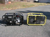
This post is for technoids so if you don't swing that way now is the time to tune out. Away we go.

I guess I'll never know the details of how these Kidde units were made. We're talking the mid 1950's time frame when technology was not so advanced. However, some really remarkable achievements were made back in those days leading to space travel, etc. The military, in particular, used a cost-no-object approach to obtain certain components and systems which met their requirements. For example, every effort was made to keep the weight of aircraft components as light as possible. A weight saving of a few ounces could be regarded as justifing a merit award to that individual or contractor. Vibration is another area of concern. Therefore, a lighter, onboard compressor with zero vibration was a goal.

The Kidde compressor began life in 1951 as a component of the F-86 jet fighter. It saw much action in the Korean war serving up high pressure should in flight engine starting be required. It probably saved more than a couple lives in the process. By 1958, a new design of this compressor emerged which was even lighter than the first model. The block was shortened and the orientation and location of the cylinders was changed. Instead of the second stage being located on bottom this position was now occupied by the fourth stage. The cylinders were now set at right angles and used screw in barrels instead of bolt on. The heads of the new design were bolted on as opposed to the old screw on heads. It was a true radial design.

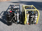
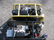
After Kidde was acquired by a British company this tradition continued while manufacturing was carried out to some extent "offshore". Kidde compressors made in the 60's carried the appellation "Rotax type" meaning the Compressor originated with this Austrian company. Regardless of who made what, the quality of construction is what intrigues me.

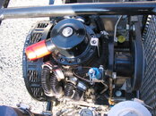
I have a lathe and can use some basic tools but in no way whould I attempt to make something to fit one of these compressors. The materials are one impediment. The pistons (3rd and 4th plungers) and valve heads (valve seats) are made from heat treated inconel which is one of the hardest metals that I have seen. The pistons are mirror polished and (as best I can determine) accurate to 0.0001 inch. I don't even know how to make a consistant measurement like that because heat from the human hand will change the micrometer reading by more than that. Moreover, my lathe has more wobble than that so I couldn't machine it in the first place. In the "factory" the Kidde was assembled by one person using parts with accuracies approximately as I've described. After machining and heat treatment the pistons and barrels were hand fitted. In other words, parts which were made to the maximum accuracy possible were than mixed and matched until a perfect fit of piston and barrel were found. (IMO, the accuracy in machining of the parts of the second generation compressor makes it a breeze to set valve and head clearance. When installing a new stage about the only really crucial measurement is that of the height of the piston and then the rest takes care of itself).When the unit was nearly complete it was mounted to a motor and run for many hours with several oil changes along the way. This is called "running in". During the run in period several performance factors were monitored including something called blow by which is the amount of gas bypassing the pistons and entering the crankcase. Typically, a commercially made compressor will have considerable blowby. Bauer allows up to 0.35-0.7 cfm. By comparison, my two Kidde pumps have no measurable blowby, none. Kidde states that anything up to 0.3 cfm is acceptable but I can tell from personal experience that is a high level and an indication of many, many hours of hard running. Blowby measurements of a pump that had more than 2500 hours of running gave 0.5 cfm. I say it was worn out but that is relative. Replacement of the fourth stage cut that number in half and the compressor had excellent pump up time. Everything else worked.

Later, I'll talk about some other design features and one or more commonly encountered problems.
 

Back
Top Bottom