Ingersoll-Rand Manual/Wiring Diagram

Please register or login

Welcome to ScubaBoard, the world's largest scuba diving community. Registration is not required to read the forums, but we encourage you to join. Joining has its benefits and enables you to participate in the discussions.

Benefits of registering include

  • Ability to post and comment on topics and discussions.
  • A Free photo gallery to share your dive photos with the world.
  • You can make this box go away

Joining is quick and easy. Log in or Register now!

dgreenh

Contributor
Scuba Instructor
Messages
359
Reaction score
37
Location
San Angelo, TX
# of dives
500 - 999
I am looking for a wiring diagram for this compressor. The Transformer went out so none of the bell and whistles work anymore. The compressor runs great but it needs a transformer. I don't believe I will be able to source one through Ingersoll-Rand so I will have to try to find something with equal output. Does anyone have any idea where one might find this sort of information.
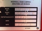
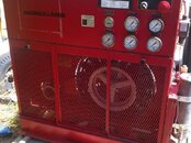
IR001.jpgir002.jpg
 
If you get a Xformer through IR you will pay 3 times what you should. Any electrical supply company can get you a xformer for around $80. You will need to know if your controls are 115 volt or 230 volt and you will need to know what voltage your input power is. And you should take the old one with you when you go.
If you are not comfortable with this the have an electrician do it. shouldn't cost any more the 300 bucks and he will supply the xformer.
ZDD
 
Thank you, I'm trying to find out what the output is supposed to be so I can find a compatible replacement. This is a friend's compressor that is about 120 miles away. It has been a while but I believe I measured the input voltage at 230. I'll measure input voltage again and see if there are any markings on the transformer itself next time I am there. I just thought there might be a manual out there somewhere that had more information.
 
Thank you, I'm trying to find out what the output is supposed to be so I can find a compatible replacement. This is a friend's compressor that is about 120 miles away. It has been a while but I believe I measured the input voltage at 230. I'll measure input voltage again and see if there are any markings on the transformer itself next time I am there. I just thought there might be a manual out there somewhere that had more information.
I used to have an large IR compressor and the controls on that were 230volts but if you check on the solenoid for the auto drain if it has one the coil may be marked with the voltage.
If not try connecting a wire to the solenoid or to the motor starter and to a 115 volt source it it does not work then try it to a 230 volt source and it should work. That will tell you.
In fact the motor starter coils usually have the voltage marked on them, try looking there first.
ZDD
 
Do your buddy a favor convince him to sell off the IR and get a nice used Bauer you will have less head ackes and parts are everywere.

Cheers
 
It has a Bauer K-14 compressor in it which runs great. Just the frame and all the other fluff on it is I-R. He is using the compressor but was wanting to get the other bells and whistles to work so he can sell it. Next time I get to see it I will search and see if I can find any voltage markings on anything. The transformer output actually goes to a circuit board to drive the lights, alarms and such. I'm guessing it will be 12v DC out but it could really be anything since this would be a custom board.
 
I'm guessing it will be 12v DC out but it could really be anything since this would be a custom board.

The transformer itself will be AC out. You may be able to look at the board and find the rectifier and voltage regulator and get some idea there. From the board pics and part nums on the IC's might help.
 
https://www.shearwater.com/products/perdix-ai/

Back
Top Bottom