Mares Puck PC Cable

Please register or login

Welcome to ScubaBoard, the world's largest scuba diving community. Registration is not required to read the forums, but we encourage you to join. Joining has its benefits and enables you to participate in the discussions.

Benefits of registering include

  • Ability to post and comment on topics and discussions.
  • A Free photo gallery to share your dive photos with the world.
  • You can make this box go away

Joining is quick and easy. Log in or Register now!

A follow up from earlier in the week.

I decided I wanted something more user friendly and travel friendly. I 3D printed a little enclosure for the circuitry. I'll share this file with anyone who is interested.

full?d=1502335162.jpg


For the Puck, the contacts are 12.1 mm apart (a little less than 1/2"). The Puck Pro has a slightly larger distance but the same distance works for both, and this interface does work for both the Puck and Puck Pro (as mentioned earlier). I have independently verified this.

full?d=1502335162.jpg


If you can find center contacts for a BNC female jack (common coaxial RF connector for ham radio), they fit onto the Puck contacts perfectly. Not so for the Puck Pro.

full?d=1502335162.jpg

Circuitry was soldered on a perf board, though if you have patience to etch your own PCB, all the more power to you. This works just fine if you aren't planning mass production.

full?d=1502335162.jpg


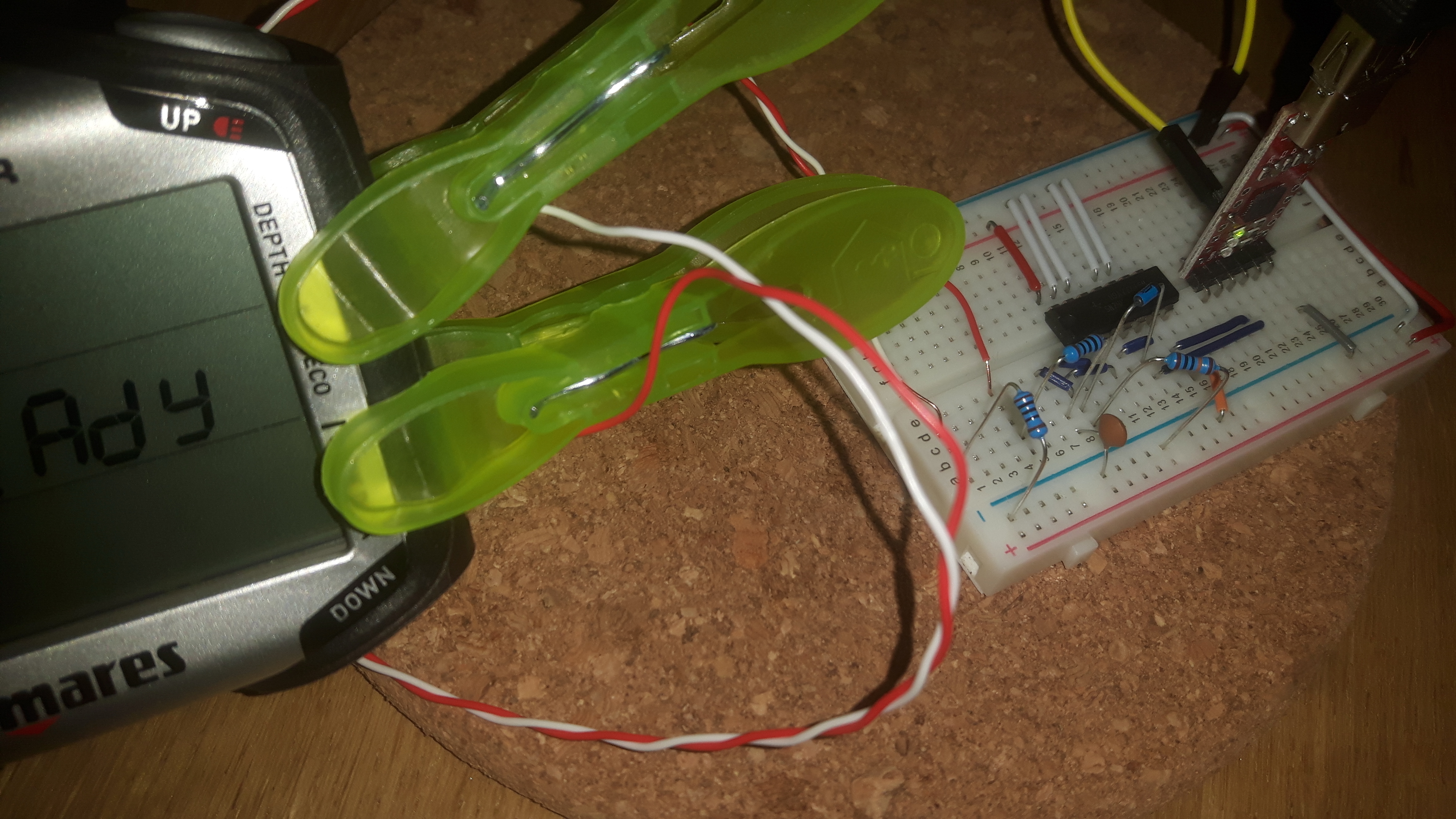
I used 6 wires to connect the CP2102 (left, in heat shrink) to the circuit (right). I used shrink tubing to hold the bundle together. The 6 pins on the CP2102 are the 3.3V, GND, SUS, !SUS, TXD, and RXD. Refer to circuitry provided by others here.

full?d=1502335162.jpg


Data and GND pins connect to the brass pins which stick through on the bottom side of the box, shown below.

full?d=1502335162.jpg


Assembled and plugged into the computer. I used a clear plastic (PETG filament) for the 3D printed enclosure so you can see the red and green LEDs.
full?d=1502335494.jpg


Plugged into the Puck. I measured the voltage with a voltmeter to determine polarity and found the GND pin to be the one nearest the strap.

full?d=1502335162.jpg
 
Hey guys! I'm really surprised to find this thread still going. I'm hoping I can get some help with my circuit. I have the Puck Pro. Using the Mares Dive Organizer, I connect the USB to TTL to my computer. The ground light stays lit for some reason and the transmit light flashes about once a second. The Dive Organizer starts searching as soon as I plug in the USB. Now with the Puck Pro in PC mode I touch the two contacts. Depending on which one touch to which contact sometimes the computer freezes sometimes nothing happens.

I have attached a picture of my circuit on the breadboard as well as the USB to TTL.
20170818_172355.jpg
20170818_172335 (2).jpg


Thanks for any help.
 
Hey guys! I'm really surprised to find this thread still going. I'm hoping I can get some help with my circuit. I have the Puck Pro. Using the Mares Dive Organizer, I connect the USB to TTL to my computer. The ground light stays lit for some reason and the transmit light flashes about once a second. The Dive Organizer starts searching as soon as I plug in the USB. Now with the Puck Pro in PC mode I touch the two contacts. Depending on which one touch to which contact sometimes the computer freezes sometimes nothing happens.

I have attached a picture of my circuit on the breadboard as well as the USB to TTL.
View attachment 422908View attachment 422909

Thanks for any help.

I see you are using the 5V pin on the CP2102. You want to use only the 3.3V pin for powering the circuit. I would disconnect the 5V to prevent yourself accidentally using it.

In addition to the pins you've connected, you could also wire up SUS and !SUS. You probably don't need them, but they help verify correct function of the circuit. I have the version which has all signal lines routed. I've attached a photo of an example of a board that has SUS pins available (SU1 and SU2). You connect these through a couple colored LEDs to monitor what's happening.
1403465045805-P-1789625.jpg


You want to carefully check your circuit against the one supplied initially by Bryscus:

mares-puck-schematic-big-jpg.137751


Not all diodes do the same job. Make sure you're using the correct type of diode (schottky diode). I used the BAT42/BAT43. It appears to me that your diode is backwards. The black bar indicates the cathode which should be connected to the second NAND gate. I can't really tell if your second gate is wired correctly from the angle of the photo. Just double check all your connections carefully against the above schematic AND the pin-out in the datasheet for your IC.

The polarity of the dive computer (DIO vs GND) can be determined by setting PC mode and measuring DC voltage with a multimeter. You should have +3V or so across the terminals. I haven't tried connecting in reverse polarity, so I don't know what might happen if the pins are backwards (I admit to not spending much time studying the circuit).


It should work with the Puck Pro. I successfully downloaded dives. I'd check your circuit with a multimeter to make sure your input impedance is high (100 kOhms). If you short out the pins, you can get the dive computer lock up on your (happened to me).

It can be tricky to get everything to connect right once it's working. I think you want to have the dive computer connected before you log into your dive organizer. It seems to search for a dive computer for only the first minute before giving up. For the Puck Pro, you probably want a clamp or clip to hold the contacts on the computer. I had to hold the contacts by hand (I built my interface for the Puck) and it was a PITA.

Good luck!
 
Thanks so much Russoft! I was indeed the backwards diode. It's been a few years since I played with circuits and I just forgot about diode polarity. Thanks for your help! I was able to download all the dive information off the computer.
 
Amazing how long this tread's been going on.

If all I wanted to do was get the firmware upgraded on my Puck Pro.... would a dealer do that for me?
 
I just want to say thank you for sharing your pictures, I was able to create my own cable, and it is working fine with my Mares Smart!
(btw: my first attempt failed, I didn't realized that you connected two legs under the Schmitt trigger (but only two))

Yep, you were right, these screws are the contacts.

I built it with the following components (less than 6€ in Germany):
- CP2102 Breakout Board
- BAT 43 diode
- SN74HC132N Schmitt trigger
- striped PCB - see the attached picture for the PCB layout (Important note: some conducting paths are cut through (beneath the ICs).)

It works with my Puck Pro! :)
Thank you all for sharing your knowledge!
 
Hi there,

last week I brought the parts for the interface and I'll try to update the firmware of my Quad. The interfaces for Puck, Puck Pro and Quad seams to be identical so I hope that it will work with the Quad. Do you know which pin shown on the photo is the gnd? I guess it's the top one.

Thanks for any help. :)

6pocb9ym.jpg
 
Ok update. I managed to connect the Quad to the PC and my DiveManager successfully detects the model, serial number and firmware version.


My Quads firmware version is 1.0 so I downloaded the latest version (2.01) and tried to update it. Surprisingly the process fails by throwing the following error: "The ENC file doesn't fit with the connected device. Please choose the right ENC file".


Are there any suggestions?
 
https://www.shearwater.com/products/teric/

Back
Top Bottom