Diy Light, 800 Lumen, 4 Power Levels

Please register or login

Welcome to ScubaBoard, the world's largest scuba diving community. Registration is not required to read the forums, but we encourage you to join. Joining has its benefits and enables you to participate in the discussions.

Benefits of registering include

  • Ability to post and comment on topics and discussions.
  • A Free photo gallery to share your dive photos with the world.
  • You can make this box go away

Joining is quick and easy. Log in or Register now!

bradsab

Contributor
Messages
163
Reaction score
1
Location
Illinois
# of dives
50 - 99
After a couple of years gleaning info from all of you, I finally have something to give back. Herein are the chronicles of a DIY light. There are some great threads here on Scubboard that helped me along the way, but most deal with making a canister light, and I wanted a self-contained flashlight that could be used above water as well.

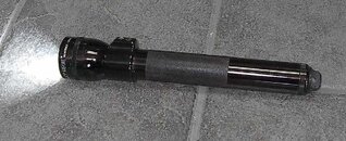
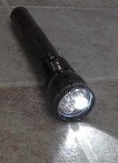
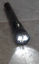
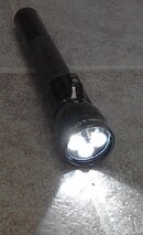
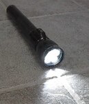
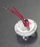
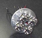
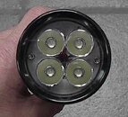
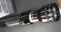
The modified 3D Maglite is rated at 800 lumens output; I don’t have a way to measure the actual out-the-front lux or lumens, but it most certainly is less. There are four power levels, accomplished by switching between 1-4 of the Seoul P4 emitters, giving 200, 400, 600 & 800 lumens output. The light is waterproof to at least 350 ffw. Burn time should be 3-4 hours at full brightness @ 800 lumens, 4-6 hours @ 600 lumens, 6-8 hours @ 400 lumens, and 12-16 hours @ 200 lumens, depending on the batteries used.

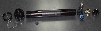
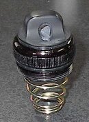
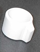
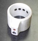
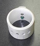
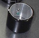
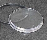
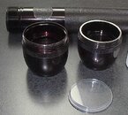
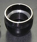
Due to the upload limitations, I will split this into several posts so I can include pictures. Sorry about the quality of the pics, the ancient camera I keep at the shop has very low resolution and no macro mode.
 

Attachments

  • Picture 069.jpg
    Picture 069.jpg
    44.1 KB · Views: 343
  • Picture 071.jpg
    Picture 071.jpg
    40.8 KB · Views: 279
  • Picture 072.jpg
    Picture 072.jpg
    49.4 KB · Views: 220
  • Picture 073.jpg
    Picture 073.jpg
    36.6 KB · Views: 203
  • Picture 070.jpg
    Picture 070.jpg
    61.9 KB · Views: 268
The disassembled Maglite looks like this. To remove the switch, peel out the rubber boot and insert a 5/64” Alan wrench into the hole in the switch button to loosen the setscrew. The switch assembly will slide out the battery end. Leave the snap-ring inside the body.
 

Attachments

  • Picture 054.jpg
    Picture 054.jpg
    46.4 KB · Views: 903
Grind a tapered edge around the switch hole. Wrap tape around a battery until a snug fit is achieved inside the body, and slide under the switch hole to form the inside. Fill the hole with urethane metal adhesive. I used Norton Speedgrip urethane P/N -04617, but I’m sure epoxy would work just as well. When set, knock the battery out and block sand the outside to the contour of the body. Sand the anodizing off the head end of the body to provide a negative ground to the LED module. Discard the body/head o-ring, and use the one from the end-cap (it’s slightly thicker).
 

Attachments

  • Picture 056.jpg
    Picture 056.jpg
    44.5 KB · Views: 529
Grind the anodizing from the center of the cap. Tape a form in place and fill with urethane. I used the center of an aerosol cap. After it sets shape on a router table and drill a hole for a lanyard. The original o-ring on the end-cap was slightly thicker than the o-ring at the body/head, and it worked perfectly there. New o-ring for the end-cap is 1-3/16" ID X 3/32" C/S.
 

Attachments

  • endcap.jpg
    endcap.jpg
    19.7 KB · Views: 270
  • Picture 077.jpg
    Picture 077.jpg
    20.3 KB · Views: 269
Cut the bulb extension off the switch housing. Leave the main hole that housed the switch, but fill the other voids with urethane. When set, cut four shallow grooves with a thin-kerf saw about ¼" apart to accommodate the reed switches. Cut grooves in the ends for bending the switch leads toward the center, so they won’t touch the snap-ring inside the body on the head end. Drill holes diagonally from the battery end of the groove into the center switch hole. Bend the lead of the reed switches and insert into the holes, and use a short wire to solder a connection between all four leads to the positive battery contact. I used these reed switches: COTO TECHNOLOGY | RI-25C | Switches | Electromechanical & Industrial Control | Newark.com Solder wire leads to each reed switch that are long enough to extend outside the head so the connection to the LED module will be easier.
 

Attachments

  • switch.jpg
    switch.jpg
    18.5 KB · Views: 276
  • switch 1.jpg
    switch 1.jpg
    22.1 KB · Views: 241
  • Picture 067.jpg
    Picture 067.jpg
    32.3 KB · Views: 243
The switch collar is made of 1 1/2" PVC pipe. The lever on the collar is made from a PVC coupler cut into fourths. Remove the ridge inside that prevents the pipe from going past halfway and glue one section to the collar. Heat another section in boiling water and form it to the one glued to the collar. After it cools, glue it on top of the first one. Shape on a router table.
With the switch housing just inside the body, mark the collar for the magnets. I used these magnets: Unsupported Browser: Reid Supply Company . Drill for a pressed fit. Check the switch operation with a multi-meter: I had some polarity issues that affected the operation of the reed switches; must have something to do with the magnets being so close together. The magnets are not as thick as the PVC collar, so once everything is in working order, fill the voids above the magnets with urethane.
Drill & tap the switch lever for a ball plunger and half-dog setscrew. I used these: Unsupported Browser: Reid Supply Company
Unsupported Browser: Reid Supply Company
The ID of the PVC is too large for the Maglight body. Line the inside with 3M Aluminum tape P/N -06930. Three layers gave a nice fit. Run the collar over the knurled area of the body to press the tape firmly onto the PVC. I painted the switch collar before applying the tape.
 

Attachments

  • collar.jpg
    collar.jpg
    11.9 KB · Views: 172
  • Picture 060.jpg
    Picture 060.jpg
    15.3 KB · Views: 167
  • Picture 061.jpg
    Picture 061.jpg
    23.3 KB · Views: 162
  • finished collar.jpg
    finished collar.jpg
    12.6 KB · Views: 184
The stepped lens is made of ¼" polycarbonate. You’ll find other ways to make this in other threads here on Scubaboard. I made an arbor/faceplate by cutting a wood disk with a hole saw and using a bolt for the arbor shaft. Cut an oversized lens and attach it to the faceplate with double-sided adhesive molding tape. Another thread here on the board suggested using hot-melt glue, and boiling it to release the glue when finished. Put the arbor in a drill press and turn the lens as you would on a lathe. Keep checking the fit to the Maglite head and lens bezel. You want the OD to fit snugly inside the bezel, and the step diameter to just fit inside the head cavity. Note that the lip of the head will be machined down to where the wall of the head is thicker, so you’ll want to make sure the lens step fits inside the smaller ID. Finish it as smoothly as possible; you can actually polish the step cut to a clear glass finish. Use the original o-ring at the head/bezel, and a 1-15/16" X 3/32" C/S o-ring on each side of the lens.
 

Attachments

  • lens.jpg
    lens.jpg
    15.4 KB · Views: 424
The head has a very thin lip next to the lens, but it widens out as you get deeper into the cavity where the LED module sits. Machine the lip down to where it gets thick. I put adhesive-backed sandpaper on the faceplate I made for turning the lens, and sanded it down on the drill press. I also sanded a small flat edge on the other end of the head so the switch collar would ride against that surface.
The cavity in the Maglite head was not quite deep enough for the LED module, and I had to have it machined .100" so the reflectors on the module cleared the lens when assembled. Wayne Johnson from Elektrolumens was very accommodating, and he might be able to build an MT-4 on a thinner heat sink, so this machining could be avoided. The heat sink he built mine on also had a small extension that protruded into the head where the threads for the body are, and I ended up machining off the end of the body to compensate for that because I had already made the collar and positioned the magnets. If the module were just a flat disk, it would be better.
 

Attachments

  • Picture 055.jpg
    Picture 055.jpg
    79.4 KB · Views: 166
  • finished head.jpg
    finished head.jpg
    13.4 KB · Views: 149
The LED module is an MT-4 from Elektrolumens Elektro Lumens Presents "Monster Throw LED Drop-ins" . The standard version comes with a cupped heat sink that normally fills the cavity in the Maglite head, and protrudes past the head the same distance the original Maglite reflector took up. The original lens would then rest on the MT-4 instead of the original reflector. Now that the head is machined for the o-ring under the lens, the protrusion would be even greater, so the cupped heat sink is not usable. Wayne will build one on a flat disk like the one shown in these pics, and as mentioned earlier, a thinner disk would be better. One thing the cupped sink does is makes the module tight because it’s sandwiched between the lens and head. Built on a disk, the module is loose in the cavity, so it has to be drilled, tapped and screwed into the head. Wayne sent 4-40 stainless screws with the module.
The standard MT-4 is made as a drop-in for the 3D Maglite, so it comes with an adapter to screw into the Maglite bulb socket, and all four LED emitters wired together. I had Wayne build the sink with a hole in the center, and each emitter wired separately. Ground them all to the heat sink base with a screw. Sand off the anodizing from the base at the area where the Maglite body makes contact when screwing it all the way into the head. (Remember, you’ve already removed the anodizing from the end of the body. This completes the negative circuit.) The four emitter leads can’t be attached to the reed switch leads until the light is assembled.
 

Attachments

  • module bottom.jpg
    module bottom.jpg
    15.3 KB · Views: 177
  • module top.jpg
    module top.jpg
    21.5 KB · Views: 230
  • Picture 076.jpg
    Picture 076.jpg
    28.1 KB · Views: 189
The reed switch assembly needs to be a good friction fit so it can’t move once the light is finished. If needed wrap some tape around it to get a good fit. Once in place, temporarily assemble the light and wrap masking tape around the body next to the switch collar. Find the ideal on/off positions for each LED emitter and mark. Then mark through the tapped holes in the collar lever for the ball plunger and half-dog set screw. Disassemble the light and cut a shallow groove for the setscrew to provide a stop at the full on and off positions, and also to keep the collar from sliding back on the body. I used a carbide bit on the router table. Then drill detents for the ball spring.
 

Attachments

  • Picture 068.jpg
    Picture 068.jpg
    71.6 KB · Views: 534
https://www.shearwater.com/products/swift/

Back
Top Bottom