Mares Puck PC Cable

Please register or login

Welcome to ScubaBoard, the world's largest scuba diving community. Registration is not required to read the forums, but we encourage you to join. Joining has its benefits and enables you to participate in the discussions.

Benefits of registering include

  • Ability to post and comment on topics and discussions.
  • A Free photo gallery to share your dive photos with the world.
  • You can make this box go away

Joining is quick and easy. Log in or Register now!

One thing to keep in mind with this gadget is that it uses a lot of battery power. Use it carefully, doing downloads of dive data possibly only after each multiple-dive trip. There are several dive computers with this problem, even Suunto. I am not shure why, because the Puck circuit above appears to have an input impedance of soime 100 kohm. However, this is only the static resistant impedance and some of the current can possibly go through the USB microboard, not visible under static conditions.

Consider the software package "Subsurface", an open source program that interacts perfectly with the Puck line of computers (and many others) and that runs on Linux, Mac as well as Windows. In my personal opinion it is great. Check it on the Web.

Kind regards,
willemf


Hello to all, my first post and a question: why do you think this dongle sucks Puck's battery? It has it's own power source (from USB) and CMOS inputs on NAND gates have very high impedance...the only common thing for them is the ground, but I hardly doubt that there is some unwanted ground return path for signal that would somehow "short-circuit" Puck with USB to serial dongle.

Yes, doing too many PC syncs could drain Puck's battery a bit faster, but I believe it would be more because of what the whole syncing procedure does to the Puck and not because this circuit might be sucking it up.
On mine, when the syncing is in progress, I hear a faint buzzing sound, as if the buzzer in the Puck is working in sync with the data going in and out...it's like I'm listening to a modem... :)
So, if something is gonna eat my battery, it would be this I presume...don't know if it's supposed to work that way...can you guys check it out with your Puck's while they are syncing?

Cheers, Andrea

---------- Post added March 20th, 2014 at 11:33 AM ----------

I think that is the answer. BAT42 is a Schottky diode unlike 1N4148

Yep, I used a Schottky diode as well, but it was what I had at hand, BAT43.

If somebody's trying to use regular silicon, give it up - Schottkys have much lower voltage barrier of around 0.2V while normal silicon diodes (PN junction actually) have 0.6-0.7V voltage barrier. In low voltage application like this, 0.5V difference might mean a difference between the signal detected correctly and not detected at all.

So, as long as you use any low power schottky diode, like BAT42/43/... you should be fine.

Cheers, Andrea
 
Thanks for the tip I changed diode to BAT85 (replacement for BAT42) but it didn't help:( I'm slowly out of options, circuit seems to be simple and I think that I made no mistake. Only difference now is that I'm using 74HC132N instead 74AC132N but I don't know the difference between them.
Thing that wonders me is that red diode is not going down when green diode blinks - how should it work?

It shouldn't matter do you use HC or AC version because they are both high speed, low voltage CMOS Schmidt NAND gates, with working voltage of 2-6V.
What you might have is a bad chip or component, or a failure in wiring/orientation of a certain component - check the circuit and the IC separatelly if you can, or replace it with another one.

BTW green led should light up when the dongle is activated by the driver and red should go on and green off when you connect the Puck.
Then, during the communication, both blink in accordance to data being transmitted.


---------- Post added March 20th, 2014 at 01:06 PM ----------

I made mine a few days ago, and as always, the mechanical part was the biggest pain in the....beehind...


I used a crocodile-type contact clip for AV meter, the largest I could find (it opens up enough to grip over a car battery poles) and then had to do some drilling and filing of the "teeth" it has in order to avoid it scratching my Puck Pro's casing.
On the tip of it (one side) I glued a piece of spongy insulator (3mm thick, quite sticky, has very tiny holes, and feels quite rubbery, reminds me of a neopren which can be used as well).

For the other tip of the clip, where the contacts are, I used a plastic cap for DVI cable. I drilled two holes in it and put two gold-plated, V-shaped springy contacts from an old battery charger that died. Then I filled it all with "liquid plastic" keeping the contacts in place with thin, long screw.
While the plastic was solidifying, I drilled a 2mm hole in the tip of the clip and put a small screw for metal that has a steep angle of it's thread, that would allow me to screw it into the "liquid" plastic when it's cool.

Afterwards, I used SMD blower to heat all of the plastic and re-melt it to a point so that the screw and the contacts are both nicely surrounded with the "liquid" plastic. Left it to cool completely and prepared the cable, which then I pulled through the hole on the back of the clip and wired it to the contacts, watching what end goes where, since it is important not to confuse data pin with ground on the Puck.

The electronics I made on a 2x3cm PCB board of my design, using regular components (didn't have all of them as SMD and couldn't be bothered to go hunting for them in electronics shops around the town). It connects to USB2serial board with short 6-wire ribbon cable and before putting it all in the case, I've tested everything with Mares's software - worked nice.

Because USB2serial board has the USB connector wired, both boards are kind of clunky and big so I decided to use regular USB cable and wire it over the USB connector on the USB2serial board. That allowed me to shorten the data cable and have a long USB cable, using at the same time the case for the electronics as I see fit.

In the end, I've put both boards, insulated with some tape, in a smallest box I could find, in which I've drilled four holes - one for USB cable, one for data cable that goes to the Puck and two for LEDs. Glued the electronics inside, put some insulating sponge inside the box and closed.

Final test with Mares's software and Subsurface - works like a charm.

I'll post the pics of the clip soon, because mechanics IS the most problematic part as always for us DIY-ers...
 
Last edited:
Hi dear DIYers,

I'm quite new to electronics/soldering and trying to translate the adapter schematics into a parts list.
Anyone willing to help me? Many thanks in advance!

(Oh, and sorry for bumping this old thread, but I think ~100€ for a simple usb adapter is just a huge a** rip-off)
 
Last edited:
My nemo wide was robed. So I need to buy a new dive computer.
I'm thinking in buy the new Mares Puck Pro.

Anybody know if this interface works for puck pro too? I don't want to buy a new interface.
 
Hi everyone,

As first thanks for schematic. I have made my interface acording to this schematic. My computer is Mares Puck Pro and interface works well with it. I have just few remarks.
First, If You want use Mares software for firmware upgrade or other stuff You cannot use any USB to serial converter. It must be supported by Mares software. I have used CP2102. For other discussed parts here I have used BAT42 diode and NXP 74HC132D.
One notice. I have made my Puck stuck few times in computer mode with no answer to button press. To solve this I have found out that best is to connect interface to USB then start Mares software and only when software asks to set Puck in PC mode then do it.
My PCB is created in eagle 5 if someone wants it.
image00002.jpg
image00003.jpg
image00004.jpg
image00005.jpg
 
Hi everyone,

As first thanks for schematic. I have made my interface acording to this schematic. My computer is Mares Puck Pro and interface works well with it. I have just few remarks.
First, If You want use Mares software for firmware upgrade or other stuff You cannot use any USB to serial converter. It must be supported by Mares software. I have used CP2102. For other discussed parts here I have used BAT42 diode and NXP 74HC132D.
One notice. I have made my Puck stuck few times in computer mode with no answer to button press. To solve this I have found out that best is to connect interface to USB then start Mares software and only when software asks to set Puck in PC mode then do it.
My PCB is created in eagle 5 if someone wants it.

HI Neo2199,
you have made a wonderfull work!!
I'm interested to buy your interface.
Please contact me by email: ingad69@hotmail.com
:wink:
 
Thanks for the tip I changed diode to BAT85 (replacement for BAT42) but it didn't help:( I'm slowly out of options, circuit seems to be simple and I think that I made no mistake. Only difference now is that I'm using 74HC132N instead 74AC132N but I don't know the difference between them.
Thing that wonders me is that red diode is not going down when green diode blinks - how should it work?
I was also facing the same problem until i found out that i was powering my whole circuit from the 5v VCC on the 2012 breakout board.. it worked perfectly once i switched it to the 3.3v output!

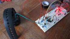
Testing it out on the breadboard helped in spotting the incorrect voltage source error!
IMG_0073.jpg


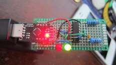
Due to my limited soldering skills i had to make all the solder connections on one side, that's why there are so many wires running on the top.. if anyone has any idea on how to make the arrangement better please let me know! I'm intending to make a few more for my friends!
IMG_0076.jpg
 
Last edited:

Back
Top Bottom