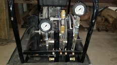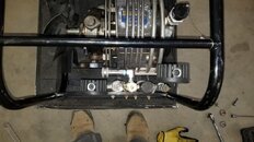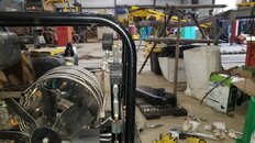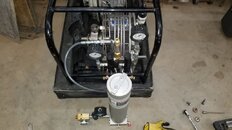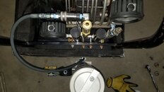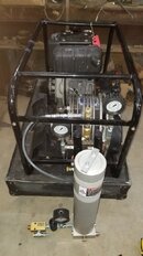


So here are some pictures with the shroud and the belt cover off. Everything moves as it should, blue spring doesn't move at all. Except for some surface rust from sitting really looks in good shape. I need to clean the excess grease off in some spots, but overall I'm pretty excited. Seems like a very well thought out / engineered unit, but also easy to service.
I'm not an expert, but pretty neat layout.
View attachment 629700 View attachment 629701 View attachment 629702 View attachment 629703 View attachment 629704 View attachment 629705 View attachment 629706 View attachment 629707
I think I've seen these compressors some place before only I thought they looked much cleaner. Memory not what it was or everything back then was much cleaner and brighter.
But just a couple of observations before I grab some sleep
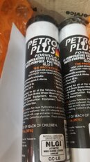
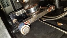
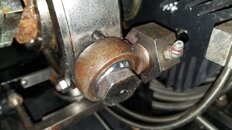
The red coloured grease you can see on those zerk grease nipples and around the second stage rod end bearing looks (from that poor small photo) to be a Lithium base soap type lubricant Its OK but only just and not the correct lubricant for the SA-6 .
When your ready consider changing to a Polyurea blue colour or color if you prefer lubricant.
Clean all that old stuff up maybe even remove those three 1" AF bolts (60 ft/ibs torque) and clean inside the rod end bearing housing also note the position of the inner ball race, by marking its postion with a black marker pen.
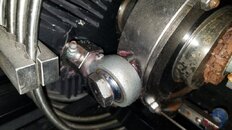
Inspect the inner ball for scuff marks at the back end and when re fitting turn the inner ball using the mark you made earlier say 90 degrees so a "new face" now touches the back end of the bearing housing. This will extend the life of thse rose head or rod end bearings no end. Re grease after 10 hours running there after every 30 hours and clean your grease mess up
In addition while the bolt is out and the inner race is all cleaned up you can assess the wear on the bronze bearing housing with a pair of automotive feeler gauges that is the part that holds the hard chromed inner ball against the hardened steel outer housing. You can do the same thing when its all assembled by pulling and pushing the piston rod back and forth to assess any play or slip, its easier to do before you clart up the bearing housing with new grease.
You can also choose to remove the entire piston rod out if you so want or leave the piston still inside the liner for all stages.
My preference at this stage would be if you remove the pistons on stage one and two only and leave the 3rd stage floating piston alone just remove the 3rd stage rod and rod end assembly Then clean up all the rods ends, and the pistons in 1 and 2
A good trick is to replace the 0 rings only on stage 1 and stage 2 but put back the old compression rings 1 & 2. Its a cheap dirty trick but it extends the spiral compression rings no end up to three times the life expectancy for the sake of a cheap viton oring that on observation you will see is scuffed and worn in two positions on stages 1 and 2
Forget doing this o-ring replacement trick on stage 3 it wont work you will damage the partially worn ring permanantly and never get them back on to the floating piston assembly 3rd stage
IMHO also dont worry to much about using industrial quality Viton 0-rings as you dont need too much the close tolerance Aircraft quality higher priced Mil Spec 0-rings Rix and ourselves use in Europe. Just make sure its Dupont Viton and not some junk from East Far pretending. Iain
")